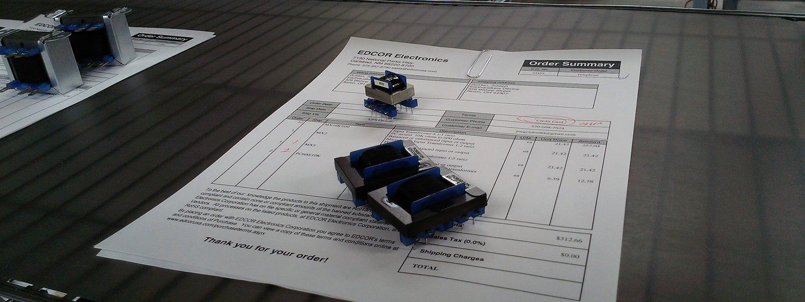
Transformers are the least understood of all electrical components. So, we thought we would give you some insight into the design.
The Power Transformer
The first item in the design is the size of the core. We must determine the output VA (volts x amps) of each winding then add them together to get the total output VA (volt-amps). First we determined what flux density we will use on the transformer. This has a direct correlation with the type of core material being used. So, by determining the type of material to use (for the core) you can get a reasonable chart to determine core size vs. VA. EDCOR only uses M6 line grain oriented silicone steel. The flux on M6 is acceptable from 0 gauss to about 17500 gauss. We chose to use about 14000 gauss (1.4 Tesla). The higher the gauss the higher the operating temperature and frequency limitations (example 50 Hz or 60 Hz). We try to work with 50 Hz to satisfy most of the world. If it works at 50 Hz it will work at 60 Hz. If it is designed at 60 Hz it may not work at 50 Hz.
The impedances are not taken into consideration, as the line delivery impedance is virtually zero until the fuse blows. The output impedance reflects the input impedance. The DC resistance is not taken into consideration. The considerations taken into the design at this point are the outputs and each of their VA. Example output #1 (300v-CT-300v 150mA) (90 VA). We need to find the turns for the primary (function of core size – low frequency – input voltage – flux density). Np has been determined with a formula based on core materials etc. Np must carry the current required to deliver all of the output needs, so we must calculate each of the output requirements. The number of turns is quite simple (Output E / Input E = turns ratio). We use a loss factor depending on the number in the total VA output (typically 1.05 so the output voltage with no load is 1.05 times, or 5%, the desired). Next is the wire size for each winding. We use 500 cma (circular mill amperes) minimum to keep the unit cool and not stress the wire or levels of winding of the wire. Keep in mind this must be figured on continuous at full current flow. The build is calculated to determine the fit. About 70% is O.K. since insulation must be used between different voltage windings. If after the transformer is designed and the build of the winding is lower than the 70%, we try to use larger wire to increase the build. If the build is over 90%, you would need to increase the core size to allow for the larger build.
The Chokes
Wow this is different. Since DC current is flowing, the unit core must be gapped to limit the magnetation of the core. The gapping and the DC current flow affects everything. We test the unit at 120 Hz and with full DC flowing in the circuit. Many test the unit with 1000 Hz. (Xl = 2piFL) We want Xl to be high at 120 Hz not at 1000 Hz. Put a bypass capacitor before and after the choke. It is virtually impossible to make a real choke above 10H at 300mA at 120 Hz at the choke frequency. It’s only a function of core weight. Take a few minutes to do the AC impedance math. The DC resistance on the choke is important as it is the (E=IR) DC voltage drop that is important to be as low as possible. A 100 Ohm choke at 300mA drops 30volts, however, the higher the inductance, the higher the DC resistance.
The Audio Transformer
The next is the audio transformer, with no DC flowing. Keep all of the above in mind and add frequency and impedance into the equation. The turns ratio is a function of impedance now, not voltage output. The square root of Zout / Zin is the turns ratio. Example 600 Ohms to 10k Ohms is 4.08 so 1v input = 4.08v output and the T.R.=4.08. The turns ratio is a direct function of E ratio and sees how it relates to Z. We do not consider any correction factor when audio T.R. is considered, except when the super power amp is driving a distribution transformer (25v ,70v ,100v, 140v, etc.) lines with multiple loads. The turns ratio will also be the voltage ratio. Most of these types transformers will be 2 or 4 ohms input and the high distribution line level voltage outputs. Exactly the way power lines work. The reverse is the speaker transformer.


